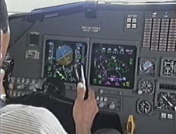
Autothrottle
(A/T) Computer Modification
On 16 November
2000, the FAA issued Airworthiness Directive (AD) number FAA AD 2000-23-34 to
replace the existing A/T computer with a new P/N. The FAA AD refers to the
Boeing Service Bulletin number SB 737-22A1130 dated 24 September 1998.
The AD was
applicable to all Boeing Model 737-300, -400, and -500 series airplanes was
effective from 8 January 2001. The AD referred to Boeing Alert Service Bulletin
number 737-22A1130 which required replacement of the previous A/T computer with
improved A/T computer Boeing P/N 10-62017-30 or 10-62017-31.
The AD addressed
the problem of split thrust lever movement caused by irregular A/T operation
which results in asymmetric thrust conditions causing the airplane to bank excessively
and going into a roll.
On 21 October
1998 Boeing issued a Service Letter (SL) number 737-SL-22-039 and on 30 April
2003 issued SL number 737-SL-22-039-A to advice the operator to incorporate the
new A/T computer with P/N 10-62017-30 (Smiths P/N 735SUE9-12, 735SUE10-12 or
755SUE2-4) or 10-62017-31 (756SUE3-4).
The
10-62017-30/31 A/T computer has been modified to address in-service reports of asymmetric
thrust events and A/T takeoff setting being oscillatory and overshooting the
target N1.
The modification
included the CTSM function and a revision to the takeoff N1 set logic. The CTSM
function is enabled when the flaps are set at less than 15 degrees.
The function
will disengage the A/T when the net thrust difference between the two engines
exceeds a limit, more than 2.5 degrees of spoiler deployment is used to control
the roll attitude of the aircraft, and the aircraft is not on takeoff or
go-around.
The A/T new P/N
refers to the A/T computer manufacturer (Smiths) SB number 735SUE-22-1266 and
735SUE-22-1267 which is to be enhanced with the following:
• Thrust Split
Monitor
• Improved T/O
N1 Set-point Algorithm
• Output ARINC
bus label 270, bit 27, changed to show internal disengagement.
• Power lever
angle (PLA) sensor validity added to disconnect logic.
• Revised
forward stop Built-In Test Equipment (BITE) test to improve reliability
• Added the
following in-flight BITE messages:
• Improved torque switch bypass logic for thrust levers moving up from aft stop.
• Corrected
several BITE nomenclature discrepancies.
The CTSM code
was reviewed by Boeing and GE Aviation with no anomalies identified. The A/T
computer manufacturer reviewed their historical documents which demonstrated
satisfactory completion of required bench testing at the time of certification.
The CTSM passed the operational test that was performed during a flight test.
This flight test was historical data obtained during the certification program.
The FAA AD
2000-23-34 was performed when the aircraft was being operated in United States
and prior to delivered to Sriwijaya Air on 2012 with the updated modification
of the A/T computer with P/N 735SUE10-12 or 755SUE2-4.
The
Test of Previously Installed Autothrottle Servo
The A/T servo
P/N 111RAA3, was manufactured by Smiths Aerospace (now General Electric/GE).
The A/T servo of P/N 111RAA3 with S/N 3480 was previously installed on the
PK-CLC aircraft and was removed from the aircraft on 22 December 2020 for A/T
problem troubleshooting. The maintenance records showed that the unit was installed
on PK-CLC aircraft since 1994.
The A/T servo
S/N 3480 was sent to Ontic facility in Chatsworth, California, United States of
America on 22 January 2021 for testing. During the conduct of the test, it was revealed
that the Ontic test bench was unserviceable and the test was rescheduled.
The A/T servo
then was sent to Ontic Cheltenham UK and was received on 12 August 2021. The
unit was immediately transferred to a secure store for a scheduled test on 9 December
2021.
On 9 December
2021, the test commenced and was witnessed by KNKT, NTSB, Boeing and AAIB UK.
Pilot
Duties and Responsibilities
Sriwijaya Air
Company Operation Manual (COM) subchapter 1.4.1 described the responsibility and authority of Pilot in Command as follow:
▪ The pilot in command of an aircraft is
directly responsible for, and is the final authority as to, the operation and
security of the aircraft.
▪ In an in-flight emergency requiring
immediate action, the pilot in command may deviate from any rule of part 91 to
the extent required to meet that emergency.
▪ The pilot in command must comply with
this Company Operations Manual, Company directives, Standard Operating
Procedures, and CASR.
The following
guidance on crew duties was provided to Sriwijaya’s pilot which was listed in
the Sriwijaya Air version of the Boeing 737-300/-500 Flight Crew Operations
Manual (FCOM),
“Normal Procedure” page NP 11.2 thru 11.4, dated March 18, 2016.
Crew
Duties
The general PF
phase of flight responsibilities are:
• taxiing
• flight path
and airspeed control
• airplane
configuration
• navigation
The general PM
phase of flight responsibilities are:
• checklist
reading
• communications
• tasks asked
for by the PF
• monitoring
taxiing, flight path, airspeed, airplane configuration, and navigation
PF and PM duties
may change during a flight. For example, the captain could be the PF during
taxi but be the PM during takeoff through landing.
The mode control
panel is the PF’s responsibility. When flying manually, the PF directs the PM
to make the changes on the mode control panel.
The captain is
the final authority for all tasks directed and done.
The crew must
always monitor:
• airplane
course
• vertical path
• speed
When selecting a
value on the MCP, verify that the respective value changes on the flight
instruments, as applicable.
The crew must
verify manually selected or automatic AFDS changes. Use the FMA to verify mode
changes for the:
• autopilot
• flight
director
• A/T
During LNAV and
VNAV operations, verify all changes to the airplane’s:
• course
• vertical path
• thrust
• speed
Announcing
changes on the FMA and thrust mode display when they occur is a good CRM
practice.
The COM
subchapter 8.1.10.6 also required PIC to report and record of mechanical irregularities
as follows:
Whenever a pilot
finds a defective equipment, the PIC will:
1. Check the
Aircraft Maintenance Log to see if the item has been previously reported and
properly deferred. If the item has not been previously written up, the PIC will
record the pertinent information on the Aircraft Maintenance Log.
2. Check the
approved Minimum Equipment List to determine if the defective equipment may be
deferred and the conditions that must be met.
3. If the
defective equipment is not deferrable, the PIC will not allow the aircraft to
take off until mechanical irregularity is corrected or acceptable Dispatch Authorization
has been issued.
Policy
on the Use of Automation
The COM
subchapter 8.3.18 described the policy on the use of automation as follow:
Automatic flight
systems are designed to enhance flight safety and efficiency and must be used
to their fullest extent.
▪ Company’s policy that the highest level
of automation appropriate to the task should be used.
▪ The Flight Crew must not allow
automation to detract from the overall management of the flight.
The Sriwijaya
Air version of the Boeing 737 CL Flight Crew Training Manual (FCTM), page 1.38
described that during all phases of flight, the use of A/T is recommended when
the A/P is engaged.
Normal
Procedure on Climb and Pass 10,000 feet
The following
guidance on climb and cruise was provided to Sriwijaya’s pilot which is listed
in the Sriwijaya Air version of the Boeing 737-300/-500 FCOM, page NP 21.39
dated June 15, 2020:
Upset
Recovery Procedure
The Sriwijaya
Air version of the Boeing 737 CL FCTM, page 7.33, described upset recovery as
follows:
For detailed
information regarding the nature of upsets, aerodynamic principles, recommended
training and other related information, refer to the Airplane Upset Prevention
& Recovery Training Aid (AUPRTA) available through your operator and on the
ICAO website.
Historically, an
upset has been defined as unintentionally exceeding any one or more of the
following conditions:
• pitch attitude
greater than 25° nose up
• pitch attitude
greater than 10° nose down
• bank angle
greater than 45°
• less than the
above parameters but flying at an airspeed inappropriate for the conditions.
The latest
revision of AUPRTA concludes that an upset condition exists any time that an
airplane is deviating from the intended airplane state. The AUPRTA has been
updated to emphasize the importance of recognition and avoidance of situations
that can lead to airplane upsets and to improve a pilot’s ability to recover control
of an airplane that deviates from the intended airplane state. An airplane upset
can involve pitch or roll angle deviations as well as inappropriate airspeeds for
the conditions.
With the focus
on upset recognition and avoidance, pilots should understand how to operate the
airplane throughout the entire operational flight envelope. Pilots should have
practical knowledge of and demonstrate proficiency in airplane performance and
handling characteristics.
Upset prevention
and recovery training should emphasize the entire operational flight envelope
to develop pilot awareness and handling skills in both manual and automated
flight.
The nose low,
high angle of bank upset requires prompt action by the pilot as altitude is
rapidly being exchanged for airspeed. Even if the airplane is at a high enough
altitude that ground impact is not an immediate concern, airspeed can rapidly
increase beyond airplane design limits. Simultaneous application of roll and
adjustment of thrust may be necessary. It may be necessary to apply nose[1]down
elevator to limit the amount of lift, which will be acting toward the ground if
the bank angle exceeds 90°. This also reduces wing angle of attack to improve roll
capability. Full aileron and spoiler input should be used if necessary to smoothly
establish a recovery roll rate toward the nearest horizon. It is important to
not increase g force or use nose-up elevator or stabilizer until approaching wings
level. The pilot should also extend the speed brakes as needed.
High
Bank Angles
If the airplane
is not in “zero-angle-of-bank” flight, lift created by the wings is not being
fully applied against gravity, and more than 1 g is required for level flight.
At bank angles
greater than 67°, level flight cannot be maintained within AFM load factor
limits. In high bank angle increasing airspeed situations, the primary objective
is to maneuver the lift of the airplane to directly oppose the force of gravity
by rolling in the shortest direction to wings level. Applying nose-up elevator
at bank angles above 60° causes no appreciable change in pitch attitude and may
exceed normal structure load limits as well as the wing angle of attack for
stall. The closer the lift vector is to vertical (wings level), the more
effective the applied g is in recovering the airplane.
A smooth
application of up to full lateral control should provide enough roll control
power to establish a very positive recovery roll rate. If full roll control application
is not satisfactory, it may even be necessary to apply some rudder in the
direction of the desired roll.
Only a small
amount of rudder is needed. Too much rudder applied too quickly or held too
long may result in loss of lateral and directional control or structural failure.
The Sriwijaya
Air version of the Boeing 737 Quick Reference Handbook (QRH), page
MAN.1.7,
described the upset recovery procedure as follows:
Historically, an
upset has been defined as unintentionally exceeding any one or more of the
following conditions:
• pitch attitude
greater than 25° nose up
• pitch attitude
greater than 10° nose down
• bank angle
greater than 45°
• less than the
above parameters but flying at an airspeed inappropriate for the conditions.
An upset
condition is now considered any time an airplane is diverting from the intended
airplane state. An airplane upset can involve pitch or roll angle deviations as
well as inappropriate airspeeds for the conditions.
The following
actions represent a logical progression for recovering the airplane.
The sequence of
actions is for guidance only and represents a series of options to be
considered and used dependent on the situation. Not all actions may be needed once
recovery is under way. If needed, use minimal pitch trim during initial recovery.
Consider careful use of rudder to aid roll control only if roll control is ineffective
and the airplane is not stalled.
These actions
assume that the airplane is not stalled. A stall condition can exist at any
attitude and can be recognized by one or more of the following:
• Stick shaker
• Buffet that
can be heavy at times
• Lack of pitch
authority
• Lack of roll
control
• Inability to
stop a descent.


