 Description extracted on the whole as written on A330-200 FCOM (=Flight Crew Operating Manual)
Note: Images relating to this Post will be uploaded soon.
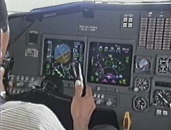
Airbus 330-200
ACARS
FLIGHT REPORTS
Flight reports provide real time information to the ground concerning the aircraft current situation and position.
Several types of flight reports are available :
the Position report: provides current aircraft position
POSITION REPORT
This report is sent:
manually via a MCDU prompt or (=Multi Function Control & Display Unit) following a ground request or automatically upon sequencing a designated reporting fix (designated by the ground in a uplink message).
The manual POSITION REPORT downlink prompt is displayed on the REPORT page POS prompt.
Img1.
Note: Position report are initiated from active flight plan only.
Img2.
POSITION report content
The downlinked message contains exactly the REPORT page data.
PROGRESS REPORT
A progress report contains data relative to the aircraft arrival time and EFOB (=Estimated Fuel On Board) at destination for the active F-PLN. (=Flight Plan)
This downlink message is automatically sent following : a ground request or a change of destination or a change of runway or a specific event. The possible events that can be selected in the navigation database policy file are:
X minutes to Top of Descent
The progress report cannot be manually sent by the crew via a dedicated MCDU prompt. =MultiFunction Control & Display Unit)
PROGRESS report content
Flight Number
FLIGHT PLAN REPORT
The F-PLN report broadcasts flight plan data to the ground. Only data from the active flight plan can be sent.
This downlink message is sent to the ground : automatically following a ground request manually by the crew using a prompt displayed on the ACARS FUNCTION page. (Refer to ACARS page description). This prompt may be invalidated through the navigation database policy file.
The Flight Plan report can be downlinked either while on ground or in flight during any flight phase.
FLIGHT PLAN report content
The report contains the active and alternate flight plan.
PERFORMANCE DATA REPORT
The Performance Data report is a downlink message that allows the transmission of performance data (GW, FUEL, CG...) relative to the active F-PLN. (= Gross Weight, Center of Gravity)
This message is automatically sent following a ground request. Manual sending is not possible.
Sends to the ground :
Current GW
The purpose of the turbulence damping function is to damp the structural modes induced by atmosphere turbulence.
The function uses the Nz accelerometer and two dedicated Ny accelerometers. The PRIMs compute a turbulence damping command, which is added to the normal law command for the elevator and the yaw damper.
This function is automatically monitored and becomes inoperative for the remainder of the flight, when a failure is detected. In addition, it may be manually inhibited by switching off the TURB DAMP pushbutton on the overhead panel, when it is considered that comfort is degraded instead of being improved, and no failure is detected.
It is only available if the following conditions are met:
Aircraft in flight.
LATERAL NORMAL LAW
When the aircraft is on the ground (in "on ground" mode), the sidestick commands the aileron and roll spoiler surface deflection. The amount of control surface deflection that results from a given amount of sidestick deflection depends upon aircraft speed. The pedals control rudder deflection through a direct mechanical linkage.
When the aircraft is in the "in flight" mode, normal law combines control of the ailerons, spoilers (except N° 1 spoilers), and rudder (for turn coordination) in the sidestick. While the system thereby gives the pilot control of the roll and heading, it also limits the roll rate and bank angle, coordinates the turns, and damps the dutch roll.
The roll rate requested by the pilot during flight is proportional to the sidestick deflection, with a maximum rate of 15° per second when the sidestick is at the stop.
When the aircraft is in "flare" mode, the lateral control is the same as in "in flight" mode.
BANK ANGLE PROTECTION
Inside the normal flight envelope, the system maintains positive spiral static stability for bank angles above 33°. If the pilot releases the sidestick at a bank angle greater than 33°, the bank angle automatically reduces to 33°.
Img3.
If the angle-of-attack protection or high speed protection is operative, the bank angle goes to 45° and no further, if the pilot holds full lateral sidestick deflection.
If the bank angle exceeds 45°, the autopilot disconnects and the FD bars disappear. The FD bars return when the bank angle decreases to less than 40°.
SIDESLIP TARGET
Should an engine failure occur, the sideslip indication is slightly modified to ensure that optimum pilot rudder application is made to achieve optimum climb performance (ailerons to neutral and spoilers retracted).
In takeoff configuration, when asymmetrical thrust is detected (30 % N1 (GE) or 0.25 EPR (PW/RR)), and at least one engine is above 80 % N1 (GE) or 1.3 EPR (PW/RR), the sideslip indication will change from yellow to blue.
Zero, beta target value for optimum performance with appropriate rudder application.
 GROUND MODE
Ground mode is active on ground. It is a direct relationship between sidestick deflection and elevator deflection without auto trim.
The THS is automatically set at 4° UP (inside the green band). Manual setting according to CG has priority for take off.
The rotation maneuver is flown in direct law with full authority.
Immediately after the aircraft becomes airborne the flight mode is progressively blended in.
The reverse process occurs after touch down.
FLIGHT MODE
The normal law flight mode is a load factor demand law with auto trim and full flight envelope protection.
It provides control of elevator and THS from the side stick controllers to achieve a load factor proportional to stick deflection, independent of speed.
With the side stick at neutral, wings level, the system maintains 1 G in pitch corrected for pitch attitude, and there is no need for the pilot to trim with speed or configuration changes.
Pitch trim is automatic in both manual mode and when the autopilot is engaged.
In normal turns (up to 33° of bank) no pitch correction is required once the turn is established.
The flight mode is active from TO to landing according to the logic (page 1).
Automatic pitch trim is frozen in the following cases:
Manual trim order
The autopilot orders are limited by the PRIM
The flight mode changes to flare mode at landing, when passing 100 feet.
Flare mode is a direct stick-to-elevator relationship (with some damping provided by load factor and pitch rate feedbacks). In addition, at 50 feet, a slight pitch down elevator order is applied, so that the pilot has to move the stick rearwards to maintain a constant path, so as to reproduce conventional aircraft aerodynamic characteristics.
Normal law provides complete flight envelope protection as follows :
The load factor is automatically limited to:
+ 2.5 g to - 1 g, slats retracted
+ 2 g to 0, slats extended
PITCH ATTITUDE PROTECTION
Pitch attitude is limited to 30° nose up (progressively reduced to 25° at low speed), and to 15° nose down (indicated by green symbols "=" on the PFD pitch scale (Refer to 1.31.40)).
HIGH ANGLE OF ATTACK PROTECTION
Under normal law, when angle of attack becomes greater than prot, the system switches the elevator control from normal mode to a protection mode in which the angle of attack is proportional to the sidestick deflection.
The autopilot will disconnect if the protection is active.
V prot, V max and V floor conditions vary according to the weight and the configuration
At takeoff prot is equal to max for 5 seconds.
FLOOR
is activated through autothrust system when:
is greater than a threshold depending on the aircraft configuration, the ground speed variation, and the difference between ground speed and air speed or, Sidestick deflection above 14° and:
pitch altitude greater than 25°, or
FLOOR inhibition: (Refer to 1.22.30).
To leave the angle of attack protection the sidestick must be pushed :
More than 8° forward, or,
HIGH SPEED PROTECTION
The aircraft automatically recovers following a high speed upset. Depending on the flight conditions (high acceleration, low pitch attitude), the High Speed Protection is activated at/or above VMO/MMO.
When it is activated, the pitch trim is frozen. Positive spiral static stability is introduced to 0° bank angle (instead of 33° in normal law), so that with the sidestick released, the aircraft always returns to a bank angle of 0°. The bank angle limit is reduced from 67° to 45°.
The High Speed Protection is deactivated when the aircraft speed decreases below VMO/MMO, where the usual normal control laws are recovered.
The autopilot disconnects when high speed protection goes active.
Note:
VMO + 4 kt MMO + 0.006
The low energy warning is computed by the PRIM's from the following inputs:
Aircraft configuration
The low energy warning is triggered during deceleration before alpha floor (unless alpha floor is triggered by stick deflection), the delay between the two warnings depends on deceleration rate.
NORMAL LAW
GENERAL
Flight control normal law provides:
3 Axis control
Flight envelope protection
Maneuver load alleviation
DESCRIPTION
The Air Data and Inertial Reference System (ADIRS) supplies temperature, anemometric barometric and inertial parameters to the EFIS system (PFD and ND) and to other user systems (FMGC, FADEC, PRIM, SEC, FWC, SFCC, ATC, GPWS, CMC, CPC).

The system includes:
three identical ADIRU's (Air Data and Inertial Reference Units).
Each ADIRU is divided in two parts, either of witch can work separately in case of failure in the other:
the ADR (Air Data Reference) part which supplies barometric altitude, speed, Mach, angle of attack, temperature and overspeed warnings.
the IR (Inertial Reference) part which supplies attitude, flight path vector, track, heading, accelerations, angular rates, ground speed, vertical speed and aircraft position.
Note:
The ADIRU gives the true heading instead of magnetic heading:
above 82° North
above 73° North between 90° and 120° West (magnetic polar region)
above 60° South
one ADIRS control panel located on the overhead panel for modes selection (NAV, ATT, OFF) and failure indications.
2 GPS receivers, which are connected to the IR part of the ADIRU's for GP/IR hybrid position calculation. four types of sensors :
pitot probes (3) static pressure probes (STAT) (6)
angle of attack sensors (AOA) (3)
total air temperature probes (TAT) (2)
These sensors are electrically heated to prevent from icing up.
eight ADMs (Air Data Modules) which convert pneumatic data from pitot and static probes into numerical data for the ADIRUs.
a switching facility for selecting ADR3 or IR3 for instrument displays in case of ADIRU 1 or 2 failure.
a MAG / TRUE pushbutton switch for polar navigation.
AC BUS provides to normal electrical supply. DC BUS provides a back up possibility through internal inverter.
PROBES LOCATION
Img6.
PROBES SCHEMATIC
Img7.
Note: ADIRU
ADIRU 1 is supplied by CAPT probes,
ADIRU 2 is supplied by F/O probes
ADIRU 3 is supplied by STBY probes and CAPT TAT
ADIRS SCHEMATIC
Fig8.
CONTROLS AND INDICATORS
OVERHEAD PANEL
Img9.
1 ADR pb sw OFF :
Air data output disconnected FAULT lt:
This amber light comes on associated with an ECAM caution if a fault is detected in the air data reference part.
2 IR pb sw
OFF: Inertial data output disconnected.
FAULT lt: This amber light comes on associated with an ECAM caution when a fault affects the respective IR.
steady : the respective IR is lost. flashing: the attitude and heading information may be recovered in ATT mode.
3 IR 1(2) (3) mode rotary sel
OFF: The ADIRU is not energized.ADR and IR data are not available.
NAV: Normal mode of operation.Supplies full inertial data to aircraft systems.
ATT: IR mode supplying only attitude and heading information if the system loses its ability to navigate.The heading must be entered through the MCDU and has to be reset frequently (about every 10 minutes).
4 ON BAT lt
Comes on amber when one or more IRS is supplied only by the aircraft battery.
It also comes on for a few seconds at the beginning of the alignment but not for a fast realignment.
Note:
if, when the aircraft is on the ground at least one ADIRU is supplied by batteries:
an external horn sounds the ADIRU light comes on amber on the SERVICE INTERPHONE BAY panel.
PEDESTAL
Img10.
1 AIR DATA and ATT HDG sel
NORM: ADIRU 1 supplies data to PFD1, ND1, DDRMI and ATC 1.ADIRU 2 supplies data to PFD2, ND2 and ATC2.
CAPT ON 3 : ADR 3 or IR 3 replaces ADR 1 or IR 1 F/O
ON 3 : ADR 3 or IR 3 replaces ADR 2 or IR 2
MAIN INSTRUMENTS PANEL
At high latitude above 82.5° North or 60.5° South (or entering the north magnetic polar region :
latitude 73.5° N and longitude between 117.5° W and 92.5° W) the ADIRUs replace magnetic heading by true heading on EFIS and DDRMI.
In addition the GRID track appears on ND.
When the aircraft is in close proximity to these regions (latitude above 82° North or 60° South or approaching the north magnetic polar region :
73° N and longitude between 90° W and 120 W) the ADIRU will trigger a message on ND "SELECT TRUE REF" requesting to change north reference.
1 NORTH REF pb sw TRUE (in): Pressing this pushbutton selects the true heading for instrument displays.
TRUE light comes on blue. The ND displays GRID track values if position is above 65° N or S. MAG (out): Magnetic heading is selected.
WARNINGS AND CAUTIONS
E / WD: FAILURE TITLEconditions
AURAL WARNING MASTER LIGHT SD PAGE CALLED LOCAL WARNING FLT PHASE INHIB
STALL WARNING (No ECAM message)
An aural stall warning is triggered when the AOA (=Angle Of Atack) is greater than a predetermined angle
This angle depends on– the Slats / Flap position– the Speed / Mach– the F / CTL law (normal, alternate / direct) Cricket + STALL (synthetic voice)
MASTER WARN NIL NIL NIL
OVERSPEED– VMO / MMO
aircraft speed / mach greater than VMO + 4 kt / MMO + 0.006
– VLE aircraft speed greater than VLE + 4 kt with L / G not uplocked or L / G doors not closed
– VFE aircraft speed greater thanVFE + 4 kt with slats or / and flaps extended.
CRC ADR 1(2)(3) FAULT SINGLE CHIME MASTER CAUT
ADR FAULT lt 1, 4, 8, 10 ADR 1+2 (1+3)(2+3) FAULT
IR 1(2)(3) FAULT IR FAULT lt 1, 4, 5, 7, 8, 10
IR 1+2 (1+3)(2+3) FAULT 1, 4, 8, 10
HDG DISCREPANCY
difference between heading on CAPT and F / O displays greater than 5° in TRUE or than 7° in MAG CHECK HDG (on ND and PFD) 4, 8
ATT DISCREPANCY
difference between roll or pitch angle displayed on CAPT and F / O PFD greater than 5° CHECK ATT (on PFD)
ALTI DISCREPANCY
difference between altitude displayed on CAPT and F / O PFD greater than:
– 500 ft if baro ref STD is selected
– 250 ft if QNH is selected CHECK ALT (on PFD)
E / WD: FAILURE TITLE
conditions
AURAL WARNING MASTER LIGHT SD PAGE CALLED LOCAL WARNING FLT PHASE INHIB
EXTREME LATITUDEA / C enters in polar area, the crew must select true reference
SINGLE CHIME MASTER CAUT NIL NIL 4, 5, 7, 8
IR NOT ALIGNED
Problem detected during IR alignment NIL
FM/IR POS DISAGREE
discrepancy between a/c position computed by FMS and position given by IRs 1, 2, 3, 4, 5, 7, 8, 9, 10
BARO REF DISCREPANCY
discrepancy between F/O and captain baro ref. 3, 4, 8
MEMO DISPLAY
IRS IN ALIGN XXX IR XXX IN ATT ALIGN
messages appear in green during an IR alignment.
the message IRS IN ALIGN becomes amber if engines are running or flashes green if IRS alignment is faulty.
TRUE NORTH REF appears in green when the NORTH REF pushbutton switch is at TRUE. The message is pulsing during 10 seconds in phase 1 or 2 or at slats extension.
ADIRS SWTG appears in green when either AIR DATA or ATT HDG selector is not in NORM position.


Nenhum comentário:
Postar um comentário